|
|
Since its inception at Xerox Corporation in the early 1970s, Ethernet has been the dominant networking protocol. Of all current networking protocols, Ethernet has, by far, the highest number of installed ports and provides the greatest cost performance relative to Token Ring, Fiber Distributed Data Interface (FDDI), and ATM for desktop connectivity. Fast Ethernet, which increased Ethernet speed from 10 to 100 megabits per second (Mbps), provided a simple, cost-effective option for backbone and server connectivity.
Gigabit Ethernet builds on top of the Ethernet protocol, but increases speed tenfold over Fast Ethernet to 1000 Mbps, or 1 gigabit per second (Gbps). This protocol, which was standardized in June 1998, promises to be a dominant player in high-speed local area network backbones and server connectivity. Since Gigabit Ethernet significantly leverages on Ethernet, customers will be able to leverage their existing knowledge base to manage and maintain gigabit networks.
The purpose of this technology brief is to provide a technical overview of Gigabit Ethernet. This paper discusses:
In order to accelerate speeds from 100 Mbps Fast Ethernet up to 1 Gbps, several changes need to be made to the physical interface. It has been decided that Gigabit Ethernet will look identical to Ethernet from the data link layer upward. The challenges involved in accelerating to 1 Gbps have been resolved by merging two technologies together: IEEE 802.3 Ethernet and ANSI X3T11 FiberChannel. Figure 1 shows how key components from each technology have been leveraged to form Gigabit Ethernet.
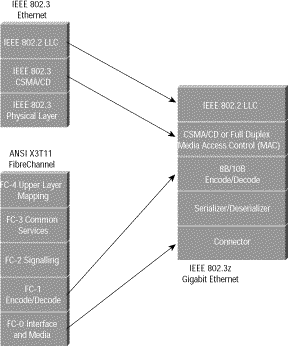
Leveraging these two technologies means that the standard can take advantage of the existing high-speed physical interface technology of FibreChannel while maintaining the IEEE 802.3 Ethernet frame format, backward compatibility for installed media, and use of full- or half-duplex carrier sense multiple access collision detect (CSMA/CD). This scenario helps minimize the technology complexity, resulting in a stable technology that can be quickly developed.
The actual model of Gigabit Ethernet is shown in Figure 2. Each of the layers will be discussed in detail.
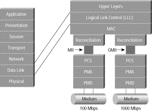
See Figure 3 for the physical diagram.
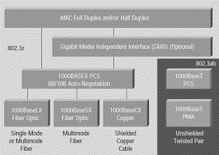
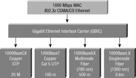
The Gigabit interface converter (GBIC) allows network managers to configure each gigabit port on a port-by-port basis for short-wave (SX), long-wave (LX), long-haul (LH), and copper physical interfaces (CX). LH GBICs extended the single-mode fiber distance from the standard 5 km to 10 km. Cisco views LH as a value add, although it's not part of the 802.3z standard, allowing switch vendors to build a single physical switch or switch module that the customer can configure for the required laser/fiber topology. As stated earlier, Gigabit Ethernet initially supports three key media: short-wave laser, long-wave laser, and short copper. In addition, fiber- optic cable comes in three types: multimode (62.5 um), multimode (50 um), and single mode. A diagram for the GBIC is shown in Figure 4.
The FiberChannel physical medium dependent (PMD) specification currently allows for 1.062-gigabaud signaling in full duplex. Gigabit Ethernet will increase this signaling rate to 1.25 Gbps. The 8B/10B encoding (to be discussed later) allows a data transmission rate of 1000 Mbps. The current connector type for FibreChannel, and therefore for Gigabit Ethernet, is the SC connector for both single-mode and multimode fiber. The Gigabit Ethernet specification calls for media support for multimode fiber-optic cable, single-mode fiber-optic cable, and a special balanced shielded 150-ohm copper cable.
In contrast, Gigabit Ethernet switches without GBICs either cannot support other lasers or need to be ordered customized to the laser types required.
Two laser standards will be supported over fiber: 1000BaseSX (short-wave laser) and 1000BaseLX (long-wave laser). Short- and long-wave lasers will be supported over multimode fiber. Two types of multimode fiber are available: 62.5 and 50 micron-diameter fibers. Long-wave lasers will be used for single-mode fiber, because this fiber is optimized for long-wave laser transmission. There is no support for short-wave laser over single-mode fiber.
The key differences between the use of long- and short-wave laser technologies are cost and distance. Lasers over fiber-optic cable take advantage of variations in attenuation in a cable. At different wavelengths, "dips" in attenuation are found over the cable. Short- and long-wave lasers take advantage of those dips and illuminate the cable at different wavelengths. Short-wave lasers are readily available because variations of these lasers are used in compact-disc technology. Long-wave lasers take advantage of attenuation dips at longer wavelengths in the cable. The net result is that although short-wave lasers will cost less, they transverse a shorter distance. In contrast, long-wave lasers are more expensive but they transverse longer distances.
Single-mode fiber has been traditionally used in the networking cable plants to achieve long distance. In Ethernet, for example, single-mode cable ranges reach up to 10 km. Single-mode fiber, using a 9-micron core and 1300-nanometer laser, demonstrate the highest-distance technology. The small core and lower-energy laser elongate the wavelength of the laser and allow it to transverse greater distances. This setup enables single-mode fiber to reach the greatest distances of all media with the least reduction in noise.
Gigabit Ethernet will be supported over two types of multimode fiber: 62.5 and 50 micron-diameter fibers. The 62.5-micron fiber is typically seen in vertical campus and building cable plants and has been used for Ethernet, Fast Ethernet, and FDDI backbone traffic. This type of fiber, however, has a lower modal bandwidth (the ability of the cable to transmit light), especially with short-wave lasers. In other words, short-wave lasers over 62.5-micron fiber will be able to transverse shorter distances than long-wave lasers. Relative to 62.5-micron fiber, the 50-micron fiber has significantly better model bandwidth characteristics and will be able to transverse longer distances with short wave lasers.
For shorter cable runs (of 25 meters or less), Gigabit Ethernet will allow transmission over a special balanced 150-ohm cable. This is a new type of shielded cable; it is not unshielded twisted-pair (UTP) or IBM Type 1 or II. In order to minimize safety and interference concerns caused by voltage differences, both transmitters and receivers will share a common ground. The return loss for each connector is limited to 20 dB to minimize transmission distortions. The connector type for 1000BaseCX will be a DB-9 connector. A new connector is being developed by AMP called the HSSDC, which will be included in the next revision of the draft.
The application for this type of cabling will be short-haul data-center interconnections and inter- or intra-rack connections. Because of the distance limitation of 25 meters, this cable will not work for interconnecting data centers to riser closets.
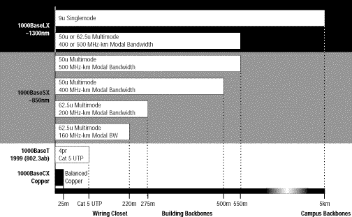
The distances for the media supported under the IEEE 802.3z standard are shown in Figure 5.
The physical media attachment (PMA) sublayer for Gigabit Ethernet is identical to the PMA for FibreChannel. The serializer/deserializer is responsible for supporting multiple encoding schemes and allowing presentation of those encoding schemes to the upper layers. Data entering the physical sublayer (PHY) will enter through the PMD and will need to support the encoding scheme appropriate to that media. The encoding scheme for FiberChannel is 8B/10B, designed specifically for fiber-optic cable transmission. Gigabit Ethernet uses a similar encoding scheme. The difference between FiberChannel and Gigabit Ethernet, however, is that FiberChannel utilizes 1.062-gigabaud signaling whereas Gigabit Ethernet utilizes 1.25-gigabaud signaling. A different encoding scheme will be required for transmission over UTP. This encoding will be performed by the UTP or 1000BaseT PHY.
The FiberChannel FC-1 layer describes the synchronization and the 8B/10B encoding scheme. FC-1 defines the transmission protocol, including serial encoding and decoding to and from the physical layer, special characters, and error control. Gigabit Ethernet utilizes the same encoding/decoding as specified in the FC-1 layer of FiberChannel. The scheme utilized is the 8B/10B encoding. This scheme is similar to the 4B/5B encoding used in FDDI; however, 4B/5B encoding was rejected for FibreChannel because of its lack of DC balance. The lack of DC balance can potentially result in data-dependent heating of lasers because a transmitter sends more 1s than 0s, resulting in higher error rates.
Encoding data transmitted at high speeds provides some advantages:
All these features have been incorporated into the FibreChannel FC-1 specification.
In Gigabit Ethernet, the FC-1 layer takes decoded data from the FC-2 layer 8 bits at a time from the reconciliation sublayer (RS), which "bridges" the FibreChannel physical interface to the IEEE 802.3 Ethernet upper layers. Encoding takes place via an 8- to 10-bit character mapping. Decoded data comprises 8 bits with a control variable. This information is, in turn, encoded into a 10-bit transmission character.
Encoding is accomplished by providing each transmission character with a name, denoted as Zxx.y. Z is the control variable that can have two values: D for Data and K for Special Character. The xx designation is the decimal value of the binary number composed of a subset of the decoded bits. The y designation is the decimal value of the binary number of remaining decoded bits. This scenario implies that there are 256 possibilities for Data (D designation) and 256 possibilities for Special Characters (K designation). However, only 12 Kxx.y values are valid transmission characters in FibreChannel. When data is received, the transmission character is decoded into one of the 256 8-bit combinations.
Gigabit Ethernet has been designed to adhere to the standard Ethernet frame format. This setup maintains compatibility with the installed base of Ethernet and Fast Ethernet products, requiring no frame translation. Figure 6 describes the IEEE 802.3/Ethernet frame format.

The original Xerox specification identified a type field, which was utilized for protocol identification. The IEEE 802.3 specification eliminated the type field, replacing it with the length field. The length field is used to identify the length in bytes of the data field. The protocol type in 802.3 frames are left to the data portion of the packet. The Logical Link Control (LLC) is responsible for providing services to the network layer regardless of media type, such as FDDI, Ethernet, Token Ring, and so on. The LLC layer makes use of LLC protocol data units (PDUs) in order to communicate between the Media Access Control (MAC) layer and the upper layers of the protocol stack. The LLC layer uses three variables to determine access into the upper layers via the LLC-PDU. Those addresses are the destination service access point (DSAP), source service access point (SSAP), and control variable. The DSAP address specifies a unique identifier within the station providing protocol information for the upper layer; the SSAP provides the same information for the source address.
The LLC defines service access for protocols that conform to the Open System Interconnection (OSI) model for network protocols. Unfortunately, many protocols do not obey the rules for those layers. Therefore, additional information must be added to the LLC in order to provide information regarding those protocols. Protocols that fall into this category include IP and IPX. The method used to provide this additional protocol information is called a Subnetwork Access Protocol, or SNAP frame. A SNAP encapsulation is indicated by the SSAP and DSAP addresses being set to "0 x AA". When that address is seen, we know that a SNAP header follows. The SNAP header is 5 bytes long: the first 3 bytes consist of the organization code, which is assigned by the IEEE; the second 2 bytes use the type value set from the original Ethernet specifications.
In the last several years, the demand on the network has increased drastically. The old 10Base5 and 10Base2 Ethernet networks were replaced by 10BaseT hubs, allowing for greater manageability of the network and the cable plant. As applications increased the demand on the network, newer, high-speed protocols such as FDDI and ATM became available. However, in the last two years, Fast Ethernet has become the backbone of choice because its simplicity and its reliance on Ethernet. The primary goal of Gigabit Ethernet is to build on that topology and knowledge base to build a higher-speed protocol without forcing customers to throw away existing networking equipment.
The standards body working on Gigabit Ethernet is the IEEE 803.2z Task Force, which has established an aggressive timetable for development of the Gigabit Ethernet standard. The possibility of a Gigabit Ethernet Standard was raised in mid-1995 after the final ratification of the Fast Ethernet Standard. By November 1995 there was enough interest to form a high-speed study group. This group met at the end of 1995 and several times during early 1996 to study the feasibility of Gigabit Ethernet. The meetings grew in attendance, reaching 150 to 200 individuals. Numerous technical contributions were offered and evaluated.
In July 1996, the 802.3z Task Force was established with the charter to develop a standard for Gigabit Ethernet. Basic concept agreement on technical contributions for the standard was achieved at the November 1996 IEEE meeting. The first draft of the standard was produced and reviewed in January 1997; the final standard was approved in June 1998.
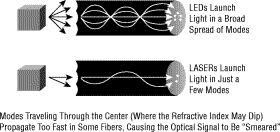
One of the delays with 802.3z was with solving the problem of differential mode delay (DMD). DMD affects only multimode fiber when using LX/LH lasers. The problem is when one mode of light experience jitters (line distortion), this could, in extreme cases, cause a single mode to be divided into two or more modes of light (see Figure 7). In other words, data would be lost. Multimode fiber was designed for short-distance Light Emitting Diodes (LEDs), not lasers.
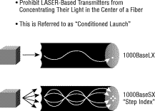
The fix is what's referred to as a "conditioned launch" (see Figure 8). In other words, if the light that travels through the center of the core---in a straight line--- is directed at a slight angle (or directed just off the center of the core), then the modal delay is corrected. To achieve a conditioned launch, a special mode-conditioning patch cable must be installed.
The timing for Gigabit Ethernet products is related to the progress of the IEEE standard activities. Any Gigabit Ethernet product design that was finalized prior to the first draft of the standard is a "guess" and potentially at risk for interoperability. Any products shipping in the first half of 1997 will fall into this prestandard category. This time frame should be a "red flag" to users who are being sold "Gigabit Ethernet" products.
After the first draft of the standard was completed, network equipment suppliers were able to develop products compliant with the draft, enabling interoperable products in the second half of 1997. Any products shipping during this time frame may not be compliant to the final standard. This time frame should be a "yellow flag" to users. The working group ballot milestone for the IEEE 802.3z Task Force was completed in June 1998.
Completion of this milestone indicates that the internal 802.3z review of the standard is complete and only public review remains. This milestone indicates a high degree of confidence in the draft standard. Network equipment vendors are now able to implement product designs with high confidence that products will be fully standards compliant. Because of the time required to develop stable application-specific integrated circuits (ASICs) and product, this timeline leads to production-worthy products in the first half of 1998.
The bottom line is that 1998 is the year for initial Gigabit Ethernet production product deployment. Cisco is investing heavily in Gigabit Ethernet technology and product development. Cisco is compliant with the IEEE 802.3z standard and ensures interoperability through work done at the University of New Hampshire (UNH) Gigabit Ethernet Consortium. UNH provides a venue for vendors of Gigabit Ethernet or other networking technologies to test their products and ensure interoperability.
A few main factors drive network scalability on the campus. First, bandwidth and latency performance become more important as existing and emerging applications are and will be requiring higher bandwidth. The typical 80/20 rule (80 percent of the network traffic is local compared to 20 percent to the backbone) is being reversed such that 80 percent of the traffic is now destined for the backbone. This setup requires the backbone to have higher bandwidth and switching capacity.
Both ATM and Gigabit Ethernet solve the issue of bandwidth. ATM provides a migration from 25 Mbps at the desktop, to 155 Mbps from the wiring closet to the core, to 622 Mbps within the core. All this technology is available and shipping today. ATM also promises 2.4 Gbps of bandwidth via OC-48, which was available and standard at the end of 1997. Ethernet currently provides 10 Mbps to the desktop, with 100 Mbps to the core. Cisco has provided Fast EtherChannel® as a mechanism of scaling the core bandwidth and providing a migration to Gigabit Ethernet.
Second, a scalable campus networking architecture must account for existing desktops and networking protocols. This scenario forces compatibility with current desktop PCs, servers, mainframes, and cabling plants. Large enterprise networks have invested millions of dollars into this infrastructure. Also, in order to ensure a smooth migration, existing LAN protocols must be supported in some way in order to assure a smooth migration.
Quality of service (QoS) has increased in visibility, as network managers require some traffic to have higher-priority access to the network relative to other traffic, particularly over the WAN. The options for QoS include Guaranteed QoS, where a particular user or "flow" is guaranteed performance, and class of service (CoS), which provides best-effort QoS, and finally, increased bandwidth such that contention for that bandwidth is no longer an issue.
Ethernet promises to provide CoS by mapping priority within the network to mechanisms such as Resource Reservation Protocol (RSVP) for IP as well as other mechanisms for Internetwork Packet Exchange (IPX). ATM guarantees QoS within the backbone and over the WAN by using such mechanisms as available bit rate (ABR), constant bit rate (CBR), variable bit rate (VBR), and unspecified bit rate (UBR).
Both ATM and Ethernet attempt to solve similar application-type problems. Traditionally, Ethernet and Fast Ethernet have been utilized for high-speed backbone and riser connectivity. A common application, for example, is to provide switched or group-switched 10 Mbps to each desktop, with Fast Ethernet connectivity to and within the core. This scenario can be accomplished at a relatively low cost. Gigabit Ethernet promises to continue scaling that bandwidth further. Recently, ATM has also been utilized to build campus-wide backbones at a moderate price range. However, the key benefit of ATM has been seen in the metropolitan-area network and in the wide-area network. WAN integration and compatibility has been a significant driver in scaling campus networks. The importance of integrating data types such as voice, video, and data over a WAN has been a significant driver for service integration and will be key in reducing the cost of WAN services and maintenance.
The following sections briefly summarize two ongoing efforts in the IEEE standards committee.
Quality of service has become increasingly important to network managers. In June 1998, the IEEE 802.1p
committee standardized a means of individual end station requesting a particular QoS of the network and the network being able to respond accordingly. This standard also specifies multicast group management.
A new protocol is defined in 802.1p, Generic Attribute Registration Protocol (GARP). GARP is a generic protocol that will be used by specific GARP applications; for example, GARP Multicast Registration Protocol (GMRP), and GARP VLAN Registration Protocol (GVRP). GMRP is defined in 802.1p; GMRP provides registration services for multicast MAC address groups.
The introduction of Virtual LANs (VLANs) into switched internetworks has created significant advantages to networking vendors because they can offer value-added features to their products such as VLAN trunking, reduction in spanning-tree recalculations effects, and broadcast control. However, with the exception of ATM LAN Emulation, there is no industry standard means of creating VLANs.
The 802.1Q committee has worked to create standards-based VLANs. This standard is based on a frame-tagging mechanism that will work over Ethernet, Fast Ethernet, Token Ring, and FDDI. The standard will allow a means of VLAN tagging over switches and routers and will allow vendor VLAN interoperability. GVRP has been introduced in 802.1Q; this protocol provides registration services for VLAN membership.
The IEEE 802.3x committee is examining a method of flow control for full-duplex Ethernet. This mechanism is set up between the two stations on the point-to-point link. If the receiving station at the end becomes congested, it can send back a frame called a "pause frame" to the source at the opposite end of the connection, instructing that station to stop sending packets for a specific period of time. The sending station waits the requested time before sending more data. The receiving station can also send a frame back to the source with a time-to-wait of zero, instructing the source to begin sending data again. (See Figure 9.)
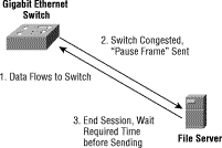
This flow-control mechanism was developed to match the sending and receiving device throughput. For example, a server can transmit to a client at a rate of 3000 pps. The client, however, may not be able to accept packets at that rate because of CPU interrupts, excessive network broadcasts, or multitasking within the system. In this example, the client sends out a pause frame and requests that the server delay transmission for a certain period of time. This mechanism, though separate from the IEEE 802.3z work, complements Gigabit Ethernet by allowing gigabit devices to participate in this flow-control mechanism.
The IEEE 802.3ab committee is examining Gigabit Ethernet transmission over UTP Category 5 cable (1000BaseT). This effort is in progress independently of the 802.3z committee and will be completed sometime after the initial version of the Gigabit Ethernet standard is complete.
Gigabit Ethernet is a viable technology that allows Ethernet to scale from 10/100 Mbps at the desktop to 100 Mbps up the riser to 1000 Mbps in the data center. By leveraging the current Ethernet standard as well as the installed base of Ethernet and Fast Ethernet switches and routers, network managers do not need to retrain and relearn a new technology in order to provide support for Gigabit Ethernet. Cisco is leading the industry by driving the standards for Gigabit Ethernet while investing in product supporting Gigabit Ethernet, Gigabit Ethernet migration paths, and ATM.
![]()
Posted: Sat Jul 1 14:44:17 PDT 2000
All contents copyright © 1992--2000 Cisco Systems, Inc. Important Notices and Privacy Statement.